|
Roof Drainage Calculations to BS EN 12056-3:2000
Gravity drainage systems inside buildings -
Part 3: Roof drainage layout and calculation
|
| Rainfall Intensity |
| BS
EN 12056-3:2000 gives rainfall intensity in litres per second per square
meter for a 2 minute storm event. For the UK, the maps in the standard
show the intensity for various return periods from 1 year to 500 years.
|
| Note the previous standard gave rainfall
intensity figures in mm per hour per square meter for 2 minute storm
event. To convert to mm/hr multiply the l/sec by 3600. |
| e.g. 0.048 l/sec is equal to 172.8mm/hr
or 75mm/hr is equal to 0.021l/sec. |
| The standard also gives four categories
of design rainfall intensity |
| Cat 1 |
Return period of 1 year |
suggested use
Eaves gutters and flat roofs |
| Cat 2 |
Return period of 1.5 x Design life of the building |
suggested use
Valley and parapet gutters for normal buildings |
| Cat 3 |
Return period of 4.5 x Design life of the building |
suggested use
Valley and parapet gutters for higher risk buildings |
| Cat 4 |
Maximum probable rainfall |
suggested use
highest risk buildings |
|
| As
an aid we have chosen a selection of towns throughout the UK, and
determined the design rainfall intensity for each town as follows:
|
- Eaves Gutters and Flat Roofs - Return
period of 1 year
- Valley and Parapet Gutter - Return
period of 50 years (Equivalent to Cat 2 with a design life of
approximately 30 years)
|
| For other design rainfall intensities
separate calculations will be required. |
| Where your project is not near one on the
towns chosen, then separate calculation will again be required. |
| If there is a town or towns that you
would like to be included please let us know |
| Gutter Types |
| The gutter shapes and sizes shown below have
been used in the preparation of the tables. Although the depth of the
gutter has most effect on the catchment area, if the gutter size
or shape varies significantly from that shown below then a separate
calculation will be required.
|
The calculated capacity is based on the gutter being:
- Nominally Level
- Freely discharging (maximum flow capacity)
|
|
|
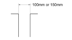
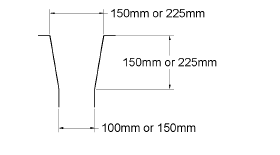
| Outlet Types - circular |
| The
diagrams below shown the size and types of outlets shown in the tables,
if other sizes or types are to be used then separate calculations will
be required. For valley and parapet gutter both results for straight and
tapered outlets are given. For eaves gutters only the results for
straight outlets are shown.
|
| Note: The roof area shown in the tables
is based on outlets with no gratings or guards. The effect of
introducing gratings or guards is to reduce the catchment area by up to
half. |
| For square outlets separate calculations
will be required |
| Straight Outlets |
 |
| Tapered Outlets |
 |
|
| Pipes |
| BS
EN 12056-3:2000 includes a calculation for the allowable capacity of the
rainwater pipes. The standard recommends that the pipe should be
designed at a maximum of 1/3rd full (Filling degree 0.33)
|
| In our calculations we have chosen two
pipe sizes and limited their capacity to 1/3rd full. |
| Note: Where there are offsets or
horizontal runs of pipes, the a separate calculation will be required to
determine the capacity of the pipe system from roof level to ground
level. |
| Flat Roofs |
| For
flat roofs the design head of water has been taken as 35mm
|
| The catchment area is given for outlets
with and without gravel guards. |
| Catchment Area |
The
catchment area given in the tables is based on the least of:
- Gutter Capacity
- Outlet Capacity
- Pipe Capacity
|
| Flat
Roofs
The catchment area can be taken as the
allowable area drained. |
| Pitched
roofs
The catchment area has to be multiplied
by the pitch factor to obtain the allowable area drained. |
Valley Gutter (only valid
where the roof pitches and slope lengths are equal.)
| Pitch |
0° |
5° |
10° |
15° |
20° |
25° |
| Factor |
1.0 |
1.01 |
1.02 |
1.04 |
1.06 |
1.10 |
|
Parapet
or Eaves Gutter
| Pitch |
0° |
5° |
10º |
15° |
20° |
25° |
| Factor |
1.0 |
0.96 |
0.93 |
0.91 |
0.90 |
0.89 |
|
| Please
Note: Where a wall or walls drain on to the roof, for example from a
higher building, then more detailed analysis of the catchment area is
required.
|
| Use of Tables |
To use the tables:
- Determine the depth of gutter required, based on the distance between
outlets
- Calculate the allowable area drained by multiplying the catchment
area by the pitch factor.
- Calculate the actual area drained from the equations given below.
- Compare the actual area drained with the allowable area drained.
- If the allowable area is greater than the actual area then the
gutter system is satisfactory.
- If not re-evaluate.
|